
The emergence of the unified modeling language (UML) as the de-facto standard for modeling software systems in architecture diagrams has encouraged the development of automated software tools that facilitate automatic code generation. UML diagrams are used to diagrammatically model and specify the static structure as well as the dynamic behavior of object-oriented systems and the software tools, then go ahead and automatically produce code from the given diagrams.
Model-driven engineering (MDE) was introduced as an engineering approach that uses models directly as primary artifacts throughout the software development life cycle (SDLC) for architecture diagrams rather than using source code.
The best known MDE initiative is the model-driven architecture (MDA) which was proposed by the object-oriented group (OMG) in 2001 as a new software development paradigm (Summerville,2009) that uses a subset of UML diagrams such as class diagrams, sequence diagrams and state diagrams. It was started because there was the necessity to decrease development efforts, create and use analysis and design models at each stage of the software development process and automate code generation from the models.
However, automatic code generation has gained a lot of attention in software engineering because it comes with a handful of benefits including reuse, being less error-prone than writing code manually, maintainability, and accuracy. Furthermore, the advantages of high-level modeling and analysis are significantly enhanced if the code can be generated automatically from a model such that the correspondence between the model and code is precisely understood.
The Motivation
Architecture diagrams have a model-system gap that exists primarily due to the different levels of abstraction. Since visual modeling is getting more and more popular, the automatic generation of the program code on the basis of high-level models is an important issue. The benefits of high-level modeling and analysis are significantly enhanced if code can be generated automatically from a model such that the correspondence between the model and code is precisely understood. Object-oriented methods help developers analyze and understand a system while working on architecture diagrams, but the Achilles’ heel of analysis and design methods has been the transition to code. Most of the object-oriented methodologies available describe sufficiently detailed steps to be followed during the analysis and design phase but fail to describe how the analysis and design models of a system shall be converted into implementation code. A big problem in the development of a system through object-oriented methodologies is that, even after having created good models, it is difficult for a large fraction of software developers to convert the design models into executable code. It would be ideal to have tools that support the developer and automatically generate or help to generate executable code from the models.
Furthermore, examining the code in a UML model for architecture diagrams enables users to identify the critical modules containing the code, enabling a starting point for understanding the business and system requirements of the preexisting system and to enable the developers to gain a better overall understanding of the source code.
The Goals to be Achieved
The final goal to be achieved while developing an architecture diagram is to automatically generate implementation code from the UML class diagrams, While the general objectives are:
1. To find an approach to generate implementation code from UML class diagrams in an object-oriented programming language such as C++.
2. To implement the proposed approach and develop a system for automatic C++ code generation from UML class diagrams. Our code generation approach and tool will help in bridging the gap between the design and development phase, this will support the developers in the software development process.

Approaches to Implementation
Generate C++ from UML (Round-Trip)
Round-trip engineering in architecture diagrams is the ability to generate models from source code and generate source code from models while keeping them synchronized. You can make use of round-trip engineering to keep your implementation model and source code up-to-date, so as to produce up-to-date documentation on your model. We are making use of class diagrams as a sample.
Most of the class diagram concepts have a one-to-one mapping with the programming language concepts. Class diagrams can be implemented directly in a programming language that supports concepts like classes and objects, composition, and inheritance.
UML to C++ transformation for class diagram
| UML | C++ |
| Class | Class |
| Interface | Interface |
| Attribute | Attribute |
| Properties on attributes | Attribute modifiers |
| Operation | Method |
| Properties on operations | Method modifiers |
| Realization between classes and interfaces | Implements |
| Generalization between classes and interfaces | Extends |
| Association between classes | Reference attributes in both classes |
There are many tools available online to perform this process, you can go through their documentation on how to use the tools, few names and respective website are provided in the table below:
UML to Source code generator tools and their website
| Tools | Website |
| Visual Paradigm | https://www.visual-paradigm.com/ |
| UModel | https://www.altova.com/ |
| StarUML | https://staruml.io/ |
| Enterprise Architect | https://sparxsystems.com/ |
| Rational Rhapsody | https://www.ibm.com/products/systems-design-rhapsody |
Some of these tools give users a free trial for a specific period of time, some may be a month while some are more than a month, also note that copyright ownership is an important issue to take into account when undertaking the process of round-trip. In some cases, software tools might have specific limitations that prohibit this process. It is also important that a user addresses the issue of copyright before kick-starting this process. Situations that typically lead themselves to round-trip include source code or UML diagrams that:
- You have already developed
- Is part of a third-party library that you have obtained permission to use
- Is part of a framework that your organization uses
- Is being developed on a daily basis by your developers.
In developing our architecture diagram, we are making use of a software tool called visual paradigm which currently supports round trip in the following programming languages:
- Java
- C++
- C#
- NET
- PHP
- ODL
- ActionScript
- Perl
- Python
- Objective C
- Ruby
- IDL
- XML Schema
Visual paradigm for architecture diagrams allows code generation in ANSI code from UML diagrams, and to reverse engineer UML class diagrams from ANSI code in the programming language listed. Check the website to get a detailed explanation on how to use this tool and others as described in the table above.
Generated C++ Code from UML Diagrams
An architecture diagram system consists of multiple statechart diagrams, each of which shows the behavior of a particular class of objects contained in the class diagram of the system. We demonstrate our code generation approach from the UML class diagrams.
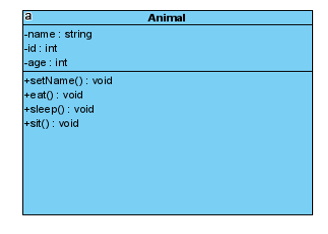
We will use a class diagram animal, to show the code generated in C++.
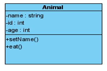
Many object-oriented tools used for round trip do generate header files from the class diagrams. Code generation from only the class diagram generates a limited skeleton code consisting of class attributes and method signatures. It provides the framework code for the object structure of a system. The generated code for the architecture diagram is incomplete and cannot be executed because the dynamic behavior of an object-oriented model system can be implemented using a statechart diagram. Based on the partial models of object dynamics, developers then explicitly program object behavior and communications in the target language e.g. (C++, Java etc.) to make it executable.
The source code for the animal class above is shown below: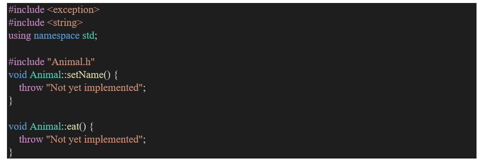
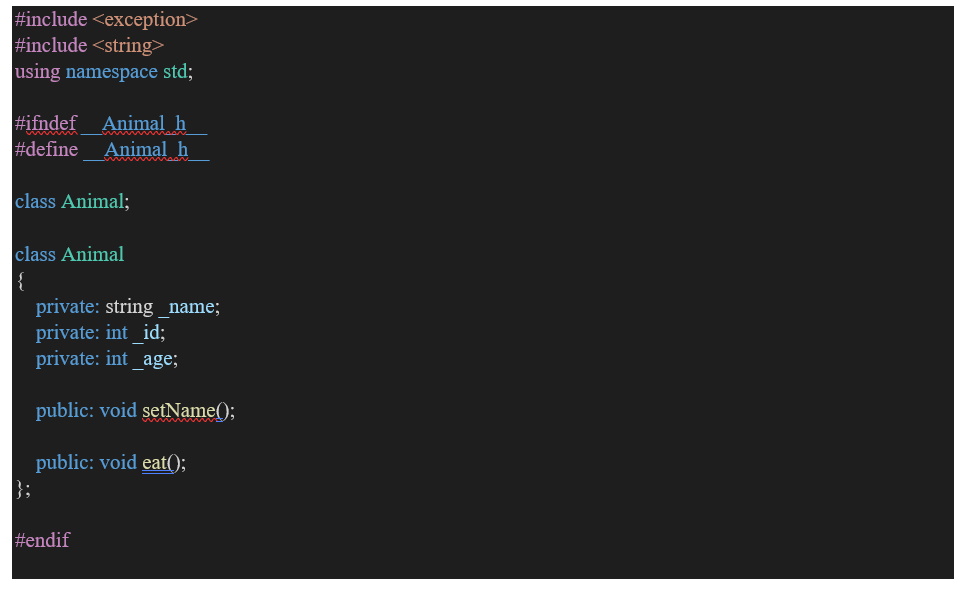
This is the animal class header file:
 This is the addition of method sleep and eat into the source code file head
The source code generated includes Class definitions, variables and function stubs for each attribute and method in the UML Class diagram animal.
The Reverse Engineering
Architectural diagrams’ Reverse Engineering is the import of existing source code into model elements, mapping the source code structures onto their UML representations. This enables you to examine legacy code and the functionality of code libraries for reuse or to bring the UML model up to date with the code. You can reverse engineer in the same languages as you perform code generation with visual paradigm.
Existing source code structures are mapped into their UML representations, for example, a C++ Class is mapped into a UML Class element with the variables being defined as attributes, and methods are modeled as operations and the interactions between the C++ Classes being displayed in the UML model Class diagram with the appropriate connectors.
Reverse Engineering enables users to examine legacy code and examine the functionality of code libraries for reuse or to bring the UML model up to date with the code that has been developed.
Examining the code in a UML model enables the user to identify the critical modules containing the code, enabling a starting point for understanding the business and system requirements of the preexisting system and to enable the developers to gain a better overall understanding of the source code also this create room for consistency as new version of software is developed and deployed for usage. This inline helps to write documentation that is:
● Inviting and clear
● Up-to-date
● Easy to find and contribute to
● Comprehensive, detailing all aspects of the project
A demonstration of reverse engineering for architecture diagrams will be shown below using visual paradigm; the source code generated above from the animal class diagram will be reversed through these steps:
1. We edit our C++ source code header file, include additional method/operation sleep and sit then save the file.
2. Import the saved file source code to visual paradigm for reverse to UML class diagram.
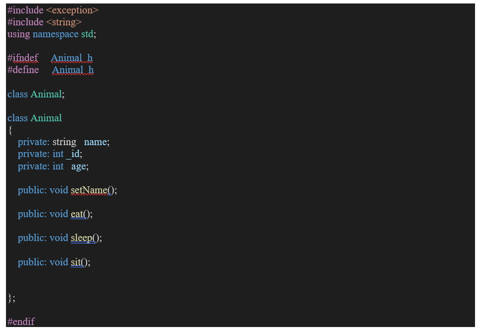
This is the addition of method sleep and eat into the source code file head

The image above shows the reversed UML Animal class diagram generated using visual paradigm as the source code is edited with addition of two method sleep and eat to the existing method.
Note: Class diagrams with relationship source code can also be generated using the same process above through visual paradigm.
Resources on relationships between UML class diagrams can be gotten online for details of how relationships are generated between different class diagrams.
Combining Class Diagram and Statechart Diagrams
Class diagrams and the statechart diagrams for architecture diagrams have to be combined for complete code generation of the entire application model. Combining class and statechart diagrams broadens the application field and covers a wider area by including static as well as behavioral information. We can now handle more complex problems containing more than one statechart and more complex statechart diagrams.
A system consists of multiple statechart diagrams, each of which shows the behavior of a particular class of objects contained in the class diagram of the system. We demonstrate our code generation approach from the UML class and statechart diagrams.
The Dishwasher System
We present an example of the Dishwasher system for architecture diagrams to show our code generation approach. This image below shows the static structure of the Dishwasher system. The architecture diagram dishwasher system consists of four classes, namely Dishwasher, Jet, Tank and Heater. The Dishwasher class has one way aggregation relationships with Jet, Tank and Heater classes. Aggregation represents a whole/part relationship. The Dishwasher represents the “whole” and Jet, Tank and Heater represent the “parts”. The Dishwasher class has four attributes namely, cycle, rinseTime, washTime and dryTime of type int.
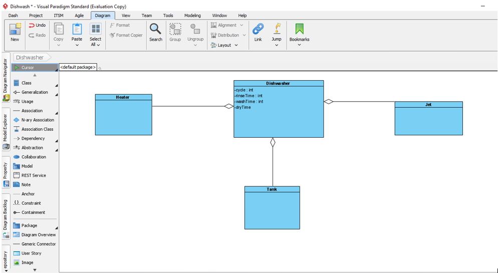
 Class diagram for the dishwasher system
The dynamic behavior of the architectural diagram Dishwasher class is specified in the statechart diagram in the next image below. It has two top-level states PowerOff and PowerOn. These states are activated alternatively whenever a powerBut event occurs. A transition from the solid circle to a state shows that the state is the default state. Initially, the Dishwasher is in the default state PowerOff, where it accepts the powerBut event. The dishwasher reacts to such an event by switching from the PowerOff state to the PowerOn state.
The PowerOn state is a composite state with two concurrent regions Active and Mode. These regions become active at the same time whenever the PowerOn state gets activated. Each of the concurrent regions has a number of sequential substates. Only one of the sequential substates becomes active at a given time. Whenever PowerOn state becomes active, DoorClosed in the Active region and Normal state in the Mode region becomes active at the same time, simply because that is the default state in each of the corresponding concurrent regions of the PowerOn composite state.
In our approach, an application class is generated in a separate file. All instances of classes in the class diagram are defined in the application class. The object instances are created once in the constructor of the application class. It also contains the main() method, which serves as an entry point for the application. The initialization code is also generated in the main() method. Separate files containing the implementation code for each class appearing in the class diagram are generated. If there is no statechart diagram for an architecture diagram attached with the class then the generated code contains only the class attributes, attributes for association with other classes and the method signatures. The behavioral aspects of a class are specified in the attached statechart diagram. If a class has an associated statechart then the generated code contains the behavior implementation for the context class in addition to the class attributes, association attributes and method signatures. In the same file the code for the state classes of the statechart diagram is also generated accordingly. The generated code is executable and contains all the information given in the application model.
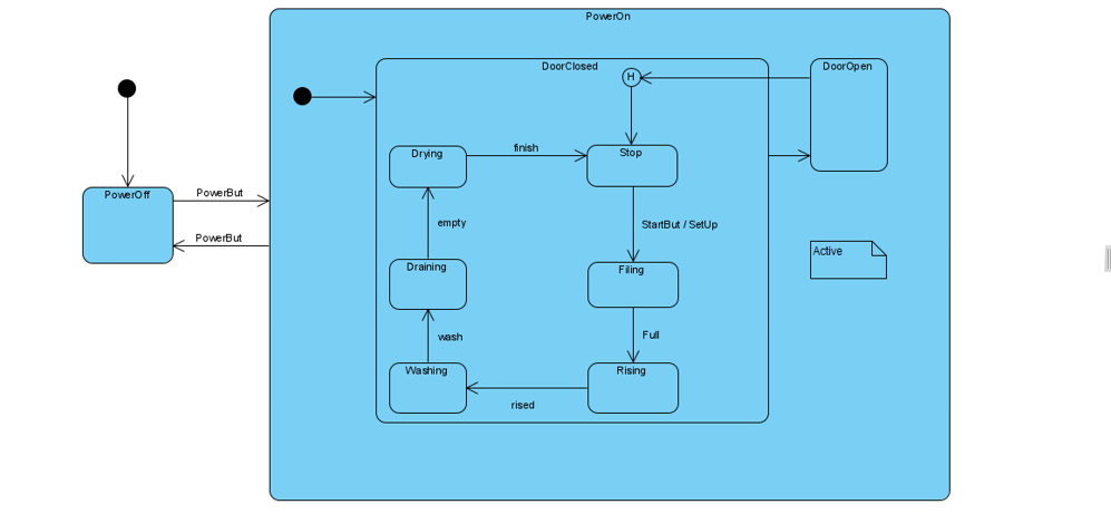

The statechart diagram of Dishwasher class
While in PowerOn state, on close or open events, the Dishwasher switches to the next sequential state in the Active region. The DoorClosed substate is a composite hierarchical state containing Stop, Filling, Rinsing, Washing, Draining and Drying sequential substates. When the DoorClosed state is active, exactly one of its sequential sub-states is also active at the same time. On open events, the dishwasher switches to DoorOpen state in the Active region. On close events, it switches into the history state of the DoorClosed state and recalls the last active substate of the DoorClosed state. An architecture diagrams’ statechart diagram describes the dynamic aspects of an object whose current behavior depends on its past. A statechart diagram in effect specifies the legal ordering of states an object goes through its lifetime. History state allows a composite state that contains sequential sub-states to remember the last sub-states that were active in it prior to the transition from the composite state.
The dynamic behavior of the Tank class is specified in the statechart diagram as shown in the next image. It has four top-level states Empty, Fill, Full and Drain. These states are activated alternatively whenever a tankFill, tankFull, tankDrain, or tankEmpty event occurs. Initially, the Tank is in the default state Empty, where it accepts the tankFill event. The Tank reacts to such an event by switching from the Empty state to the Fill state.
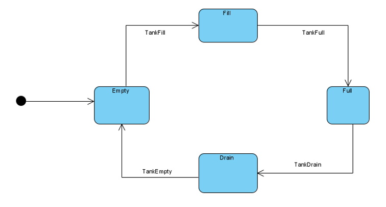
 The statechart diagram of Tank class
The dynamic behavior of the Jet class diagram during the development of an architectural diagram is specified on the statechart diagram as shown in the next image. It has two top-level states Idle and Running. Initially, the Jet is in the default state Idle, where it accepts the jetOn event. The Jet reacts to such an event by switching from the Idle state to the Running state. The Running state is a composite hierarchical state containing two sequential sub-state Spraying and Pulsing. Only one of the sequential sub-states becomes active at a given time. Whenever Running state becomes active, the Spraying state becomes active at the same time as it is the default state of the composite Running state. While in Running state, on jetPulse events, the tank switches to the next sequential sub-state Pulsing. On jetOff events, the Jet switches back to Idle state. The dynamic behavior of the Jet class is specified on the statechart. It has two top-level states Idle and Running. Initially, the Jet is in the default state Idle, where it accepts the jetOn event. The Jet reacts to such an event by switching from the Idle state to the Running state. The Running state is a composite hierarchical state containing two sequential sub-state Spraying and Pulsing. Only one of the sequential sub-states becomes active at a given time. Whenever Running state becomes active, the Spraying state becomes active at the same time as it is the default state of the composite Running state. While in Running state, on jetPulse events, the tank switches to the next sequential sub-state Pulsing. On jetOff events, the Jet switches back to Idle state.
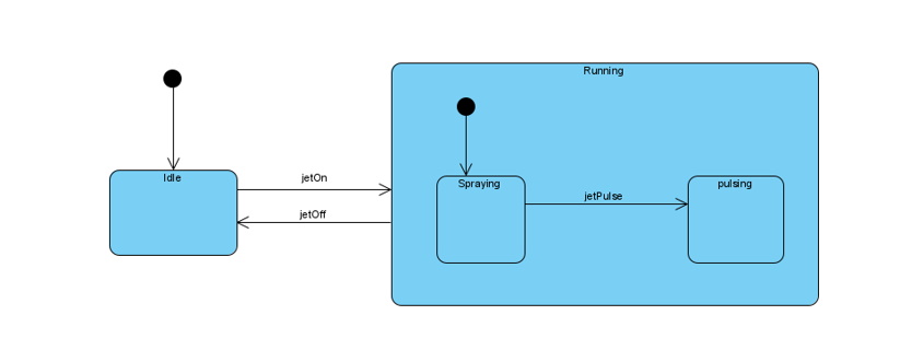
 The statechart diagram of Jet class
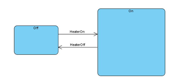

The statechart diagram of heater class
The dynamic behavior of the Heater class while developing an architecture diagram is specified in the statechart diagram as shown above. It has two top-level states, Off and On. Initially, the Heater is in the default state Off, where it accepts the heaterOn event. The heater reacts on such an event by switching from the Off state to the On state. On the heaterOff event it switches back to the Off state.
Code Generation Tools Overview
Architecture diagrams UML code generation approach in C++ will be demonstrated here by generating code for the dishwasher system diagram that was discussed previously. The visual paradigm tool system works in three major modules, namely class diagram module, statechart diagram module and the code generation module. Following is the brief description of each of the modules.
Class Diagram Module
The source code shown below is generated using visual paradigm, of the dishwasher class header file. It consists of the declaration of all other classes that have relationship with the dishwasher class as shown in the dishwasher statechart diagram above .Other classes have their header file as well being generated by visual paradigm.
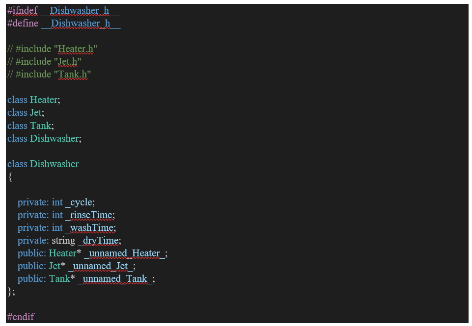

Generated code for the dishwasher class
The class diagram module reads the specifications of the class diagram, identifies various components of the class diagram and stores them in a table of classes. Nodes in DSL (Domain Specific Language) represent the classes. All the information about a class which includes name of the class, its attributes and method headers is stored. Arcs in DSL represent the relationships between classes. All the information about the relationship is also stored in the table. The class diagram module then processes the class table and extracts the statechart DSL filenames and passes this information to the statechart module to process the associated statechart diagrams. You can read more on DSL Wikipedia.
Statechart Diagram Module
The statechart diagram module for architecture diagrams receives the statechart diagram DSL filenames from the class diagram module and it then reads the corresponding input statechart diagram DSL file and records the information of the statechart diagram into a state table, thus transforming the information from DSL format to a table format.
The statechart diagram module then processes the state table and removes the information of the pseudo states (Initial, History, Fork and Join etc.) from the state table and updates the table accordingly.
The statechart diagram module returns the transformed state table back to the class diagram module. The state table is stored in the table along with other information of the corresponding class.
Code Generation Module
In the code generation module for architecture diagrams, the tools take information from the class and state tables to generate the C++ code for the entire application model following our proposed code generation approach.
In our approach, an application class is generated with a main() method that acts as an entry point to the whole system. For the dishwasher system, as shown in Figure 3.1, the main application class Dishwasher, is generated. The name of the class is derived from the project name specified in the input class diagram DSL file. All the instances of classes of the class diagram are declared and initialized in the constructor of this class. The application object is created and initialized in the main() method.
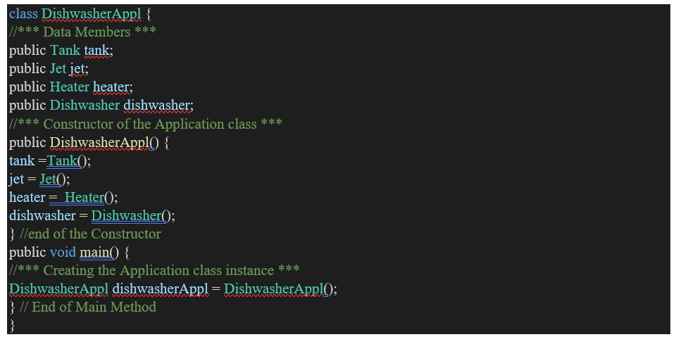
 Generated code for the application class of dishwasher system
Classes in the Class Diagram
All classes within the class diagram for architecture diagrams are transformed into C++ code. For each class of the class diagram, a separate file with (.cpp) extension and the header file with (.h) extension are generated. The generated code contains all the class definitions of name, attributes and methods. Relationships between classes are identified and transformed into code. To implement the associations between classes, reference attributes with public visibility are generated in the corresponding classes. If the association is bidirectional then reference attributes are generated in both classes and if the association is unidirectional then reference attribute is generated in the source class only.
Conclusion
In achieving our aim at developing an Architectural Diagram, an object-oriented approach has been proposed to convert the UML class diagram into implementation code. This approach generates compact and efficient executable code for the entire application model. The generated code contains the structural as well as behavioral code for all the classes of the application model.
This approach has been implemented in our sample, using visual paradigm, which automatically converts the UML class diagrams specifications into C++ source code.
Our approach is an object-oriented approach and in the present study we have used C++ as the target language for architecture diagrams. However our approach is general so it can be used to generate the low level code in other object-oriented languages. The code generation engine has to be tailored to the target language as some of the features are implemented differently in different object-oriented programming languages.